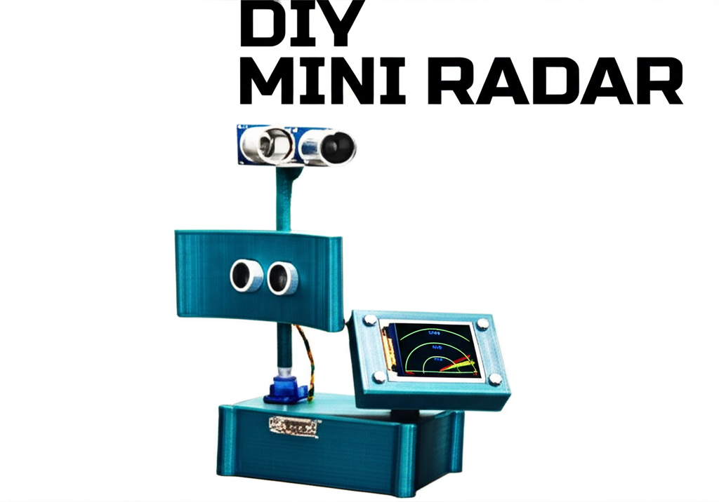
Mini Radar System using Arduino Uno
Introduction
Ever wondered how radar systems work in defense or aviation? What if you could create a mini version of it right at home using an Arduino? Introducing the Mini Radar System using Arduino Uno – a simple yet powerful electronics project that brings radar technology to your fingertips. Whether you’re an engineering student, hobbyist, or a maker, this project helps you understand object detection, real-time scanning, and microcontroller interfacing.
In this comprehensive blog post, we’ll walk you through everything – from circuit diagrams to code, components, working principles, and a live graphical display using a TFT screen.
Table of Contents
What is a Mini Radar System?
Features and Benefits
Components Required
Circuit Diagram and Pin Connections
Working Principle
Arduino Code Overview
TFT Display Output and Visualization
Object Detection with Speed Calculation
Applications of Mini Radar System
Advantages and Limitations
Future Scope
Final Thoughts
Full Code (Programming) this Mini Radar System
1. What is a Mini Radar System?
A Mini Radar System is a simplified version of a real radar that scans its surroundings using an ultrasonic sensor. It rotates with the help of a servo motor and detects any object in its range. The detected object’s distance, angle, and speed are calculated and displayed both numerically and graphically on a TFT screen.
This system uses:
Ultrasonic sensor (HC-SR04) for measuring distance.
Servo motor (SG90) for rotation (scanning 0 to 180 degrees).
TFT display (ST7735) for radar-like visuals.
Arduino Uno as the control unit.
2. Features and Benefits
🔹 Graphical display with real-time radar sweep
🔹 Object detection and distance measurement
🔹 Object speed calculation
🔹 Visual and digital output
🔹 Buzzer and LED alerts
🔹 Welcome message with creator’s name
🔹 History tracking of object movement
🔹 Low cost and beginner-friendly
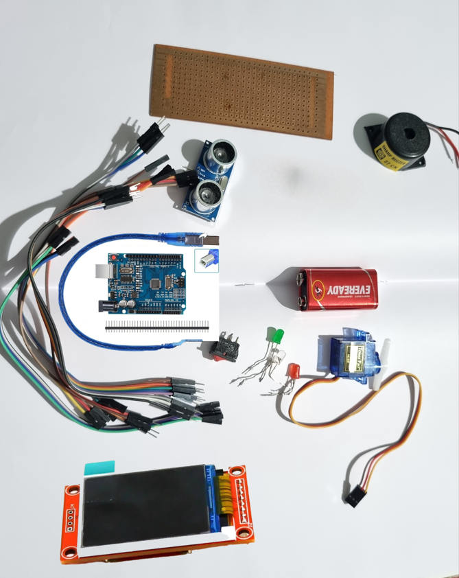
3. Components Required
| Component | Quantity |
|---|---|
| Arduino Uno | 1 |
| Ultrasonic Sensor (HC-SR04) | 1 |
| Servo Motor (SG90) | 1 |
| TFT Display (ST7735) | 1 |
| Buzzer | 1 |
| Red LED | 1 |
| Green LED | 1 |
| Jumper Wires | As needed |
| Switch | 1 |
| 9V Battery with Clip | 1 |
| Breadboard or Perfboard | 1 |
| Resistors | 2 |
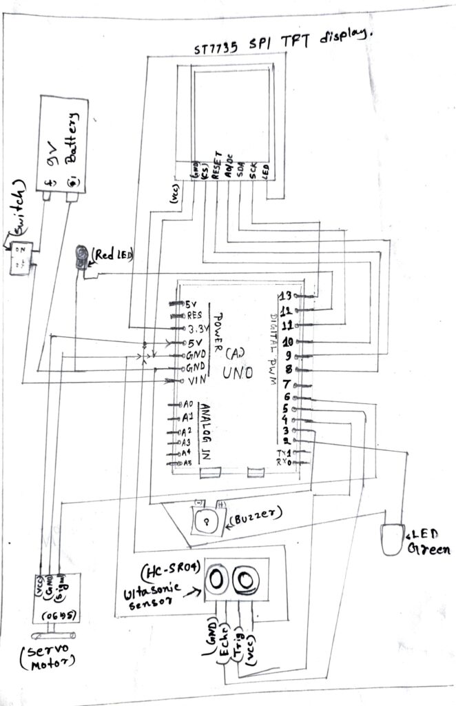
4. Circuit Diagram and Pin Connections
TFT Display (ST7735 SPI):
| TFT Pin | Arduino Pin |
|---|---|
| VCC | 5V |
| GND | GND |
| CS | D10 |
| RESET | D8 |
| A0/DC | D9 |
| SDA | D11 |
| SCK | D13 |
| LED | 3.3V or D7 (via 220Ω resistor) |
Ultrasonic Sensor (HC-SR04):
| Sensor Pin | Arduino Pin |
|---|---|
| VCC | 5V |
| GND | GND |
| TRIG | D4 |
| ECHO | D5 |
Servo Motor (SG90):
| Servo Pin | Arduino Pin |
|---|---|
| VCC | 5V |
| GND | GND |
| Signal | D6 |
Others:
| Component | Arduino Pin |
|---|---|
| Buzzer | D3 |
| RED LED | D2 |
| GREEN LED |
D12 |
Battery: 9v(Any 5v to 9v Battery use)
Circuit Diagram image :
5. Working Principle :
🔧 Working Principle in Mini Radar System
The Mini Radar System using Arduino Uno operates on the fundamental principle of ultrasonic distance measurement combined with servo-based angular scanning and graphical visualization on a TFT display. This section explains how each component works in coordination to emulate a real-world radar system in a miniaturized format.
🧠 1. Understanding the Core Technology: Ultrasonic Sensing
At the heart of this system is the HC-SR04 ultrasonic sensor, which uses sonar technology to detect the presence and distance of objects. The sensor emits a short burst of ultrasonic sound waves (at 40 kHz) through its trigger pin. These waves travel through the air until they hit an object and bounce back toward the sensor’s echo pin.
The time taken for the waves to return is recorded using the Arduino’s internal timer. This round-trip time is used to calculate the distance between the sensor and the object using the speed of sound in air (approximately 343 meters per second or 0.034 cm/µs).
📌 Formula Used:
distance = (duration * 0.034) / 2;
duration= time taken in microseconds0.034= speed of sound in cm/µsDivision by 2 accounts for the forward and return trip of the sound wave
🔁 2. Rotational Scanning Using Servo Motor
The servo motor (SG90) is responsible for sweeping the ultrasonic sensor across a 180° arc. It receives a PWM signal from the Arduino, which instructs it to rotate to a specific angle (from 0° to 180° and back).
At every 1-degree step, the sensor takes a distance measurement. This allows the system to build a complete scan of the surroundings in a semi-circular field of view.
Each angle–distance pair is then mapped to coordinates on the display to simulate a radar screen.
🧮 3. Distance & Speed Calculation
Every time a new distance reading is taken, the Arduino also compares it with the previous value. By using the time difference between readings, it calculates the speed of the object (in cm/s), which is useful for detecting moving objects and estimating how fast they approach or move away.
📌 Speed Formula:
speed = (current_distance - previous_distance) / (time_interval_in_seconds);
Speed values are shown on the TFT screen in real-time, updating with every radar sweep.
📊 4. TFT Display Radar Visualization
The ST7735 TFT Display provides a graphical representation of the radar’s output. The radar interface includes:
A semi-circular arc representing the scanning area
Radial lines marking angles (every 30° or 45°)
Concentric circles marking distances (e.g., every 10 cm)
A moving line representing the servo angle (like a radar sweep arm)
Red dots marking the detected object
Trail or history points to show object movement over time
Digital values of angle, distance, and speed printed on the screen
This dual-mode output (graphical + numerical) enhances user interaction and data readability.
🚨 5. Alert Mechanism
To enhance safety and interactivity, the system uses:
Red LED and buzzer when an object is detected within a critical range (e.g., < 20 cm)
Green LED when no immediate threat is detected
This alert mechanism provides real-time feedback, making it suitable for use in surveillance or robotics environments.
👋 6. Startup Interface & Identification
When the system is powered on via a 9V battery and toggle switch, it displays a welcome screen:
Welcome to Radar System
Created by Manjit S
Department of ETCE
This branding adds a personal and academic signature to the project and demonstrates user interface design.
🔁 7. Continuous Loop Execution
Once initialized, the system continuously runs in a loop:
Servo moves from 0° to 180° and back
At each angle:
Distance is measured
Speed is calculated
TFT is updated
Alerts are triggered if needed
The loop ensures the radar system works in real-time, continuously monitoring for any changes or new objects.
🔌 8. Power Supply Considerations
The whole system is powered by a 9V battery connected via an ON/OFF switch. The Arduino regulates this input to 5V, which powers the servo, ultrasonic sensor, LEDs, buzzer, and display.
For longer use, a rechargeable battery or USB power bank with step-down converter is recommended.
6. Arduino Code Overview
The project uses the Adafruit ST7735 and GFX library for display. Code flow:
✅ Initialize TFT, display welcome message
✅ Rotate servo and take readings
✅ Calculate distance & speed
✅ Show digital and graphical radar display
✅ Store and show object history
You can Download the Full Arduino Code Here (Link if hosting the file).
7. TFT Display Output and Visualization
The display shows:
Radar arc with degree marks
Red dot representing object position
Digital values: Distance (cm), Speed (cm/s), Angle (deg)
Radar history trail of object motion
Boot-up welcome message:
“Welcome to Radar System – Created by Manjit S, Dept. of ETCE” (Change this message)
✅ You can also add your logo or watermark on the screen using bitmap drawing.
8. Object Detection with Speed Calculation
Speed = (Current Distance – Previous Distance) / Time
It updates speed when object is in motion. Display updates every ~500ms to ensure accuracy. The graph also shows motion trail to visualize path history.
You can improve speed detection using Kalman filtering or multiple distance averaging.
9. Applications of Mini Radar System
✔️ Robotics navigation
✔️ Indoor object detection
✔️ Educational model for radar
✔️ Smart surveillance systems
✔️ Military radar demonstrations
✔️ DIY automation projects
10. Advantages and Limitations
✅ Advantages:
-
Cost-effective
-
Fully Arduino-based
-
Great for beginners
-
Reusable components
-
Visual and digital data together
❌ Limitations:
-
Limited range (2cm – 400cm)
-
No 360° rotation (only 180°)
-
Can detect false positives in noisy environments
11. Future Scope
🚀 Add Bluetooth/Wi-Fi for remote monitoring
🚀 Upgrade to 360° scanning using stepper motor
🚀 Integrate object recognition with AI camera
🚀 Add SD card logging for object history
🚀 Replace display with OLED or touch UI
12. Final Thoughts
The Mini Radar System using Arduino Uno is more than just a college project – it’s a working prototype of real-world radar systems. From real-time scanning to speed detection and history tracking, this project covers both hardware and software fundamentals. Whether you’re learning Arduino or building a smart system, this radar project is your perfect start.
13. Full Code (Programming) this Mini Radar System Arduino Uno :
#include <Servo.h>
#include <Adafruit_GFX.h>
#include <Adafruit_ST7735.h>
#include <SPI.h>
// Color constants
#define BLACK 0x0000
#define WHITE 0xFFFF
#define RED 0xF800
#define GREEN 0x07E0
// Component pins
#define trigPin 4
#define echoPin 5
#define servoPin 6
#define buzzer 3
#define redLED 2
#define greenLED 12
// TFT SPI pins
#define TFT_CS 10
#define TFT_RST 8
#define TFT_DC 9
Servo myServo;
Adafruit_ST7735 tft = Adafruit_ST7735(TFT_CS, TFT_DC, TFT_RST);
int angle = 0;
long duration;
int distance;
int lastX = 0, lastY = 0;
void setup() {
Serial.begin(9600);
pinMode(trigPin, OUTPUT);
pinMode(echoPin, INPUT);
pinMode(buzzer, OUTPUT);
pinMode(redLED, OUTPUT);
pinMode(greenLED, OUTPUT);
myServo.attach(servoPin);
tft.initR(INITR_BLACKTAB);
tft.setRotation(1);
tft.fillScreen(BLACK);
// Draw static radar background
drawRadarBackground();
tft.setTextColor(WHITE);
tft.setTextSize(1);
}
void loop() {
for (angle = 0; angle <= 180; angle += 5) {
scanAndDisplay(angle);
}
for (angle = 180; angle >= 0; angle -= 5) {
scanAndDisplay(angle);
}
}
void drawRadarBackground() {
// Draw radar circles
for (int r = 20; r <= 100; r += 20) {
tft.drawCircle(80, 64, r, GREEN);
}
// Draw angle lines
for (int a = 0; a <= 180; a += 30) {
float rad = radians(a);
int x = 80 + 100 * cos(rad);
int y = 64 – 100 * sin(rad);
tft.drawLine(80, 64, x, y, GREEN);
}
// Labels
tft.setCursor(5, 0);
tft.print(“Radar System”);
}
void scanAndDisplay(int angle) {
myServo.write(angle);
delay(100);
// Trigger sensor
digitalWrite(trigPin, LOW);
delayMicroseconds(2);
digitalWrite(trigPin, HIGH);
delayMicroseconds(10);
digitalWrite(trigPin, LOW);
duration = pulseIn(echoPin, HIGH);
distance = duration * 0.034 / 2;
// Erase last sweep line
if (lastX != 0 && lastY != 0)
tft.drawLine(80, 64, lastX, lastY, BLACK);
// Calculate new sweep endpoint
float rad = radians(angle);
int sx = 80 + 100 * cos(rad);
int sy = 64 – 100 * sin(rad);
tft.drawLine(80, 64, sx, sy, GREEN);
lastX = sx;
lastY = sy;
// Erase old text
tft.fillRect(5, 110, 150, 20, BLACK);
// Display angle and distance
tft.setCursor(5, 110);
tft.print(“Angle: “);
tft.print(angle);
tft.print(” Dist: “);
tft.print(distance);
tft.print(“cm”);
// Draw detection point
if (distance > 2 && distance < 100) {
int dx = 80 + distance * cos(rad);
int dy = 64 – distance * sin(rad);
tft.fillCircle(dx, dy, 3, RED);
}
// Alerts
if (distance > 0 && distance < 20) {
digitalWrite(buzzer, HIGH);
digitalWrite(redLED, HIGH);
digitalWrite(greenLED, LOW);
} else {
digitalWrite(buzzer, LOW);
digitalWrite(redLED, LOW);
digitalWrite(greenLED, HIGH);
}
// Debug
Serial.print(“Angle: “);
Serial.print(angle);
Serial.print(” | Distance: “);
Serial.println(distance);
}
Conclusion
This DIY Mini Radar System using Arduino Uno is a brilliant starter project for electronics and embedded systems learners. It demonstrates the integration of sensors, display technology, and microcontroller logic to create a fully functional, interactive object detection system.
If you’re an engineering student or a DIY enthusiast, this radar system is the perfect platform to kickstart your Arduino and IoT journey.
Created by: Manajit S
Department: Electronics and Telecommunication Engineering (ETCE), (SGP)